chipKIT® Development Platform
Inspired by Arduino™
- Get Started
- Learning
- Products
- Blog
- Beginner
For first time users of chipKIT modules. - Intermediate
For users who have a moderate exposure with chipKIT modules. - Advanced
For users who are experts with chipKIT modules. - Developers
- About Us
- Support
Line Following Robot with Arduino Shield
Posted 2017-02-13 09:57:21 by MajenkoOVERVIEW:
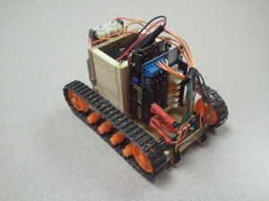
Here is a fairly basic robot application that implements a line following algorithm. This application uses off the shelf components along with a very basic chassis built from common materials. This could be a good weekend project. The Line-Follower chassis for this Demo was constructed with 2½" wide by ¼" thick poplar project wood purchased at a local home improvement center. Note that a box was also created to house the battery holder.
HARDWARE USED
- Arduino Motor Shield: http://arduino.cc/en/Main/ArduinoMotorShieldR3
- chipKIT Uno32 Development Board: http://www.digilentinc.com/Products/Detail.cfm?NavPath=2,892,893&Prod=CHIPKIT-UNO32
- Sparkfun QRE1113 Light Sensor Board - Analog (item#: ROB-09453): https://www.sparkfun.com/products/9453
- Tamiya 70100 Track and Wheel Set: http://www.tamiyausa.com/product/item.php?product-id=70100
- Tamiya 70168 Double Gearbox: https://www.tamiyausa.com/product/item.php?product-id=70168
- 6 x AA Batteries and Holder
CONSTRUCTION
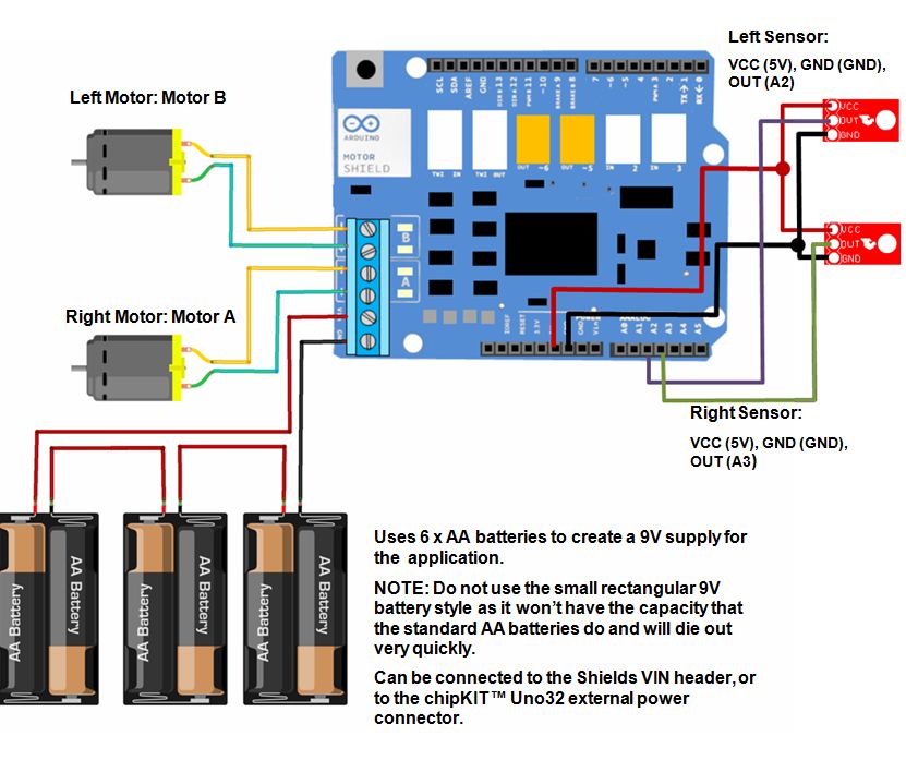
The Arduino Motor Shield is mounted to a chipKIT Uno32 Development Platform with all component connections made to the shield as indicated in labels next to component.
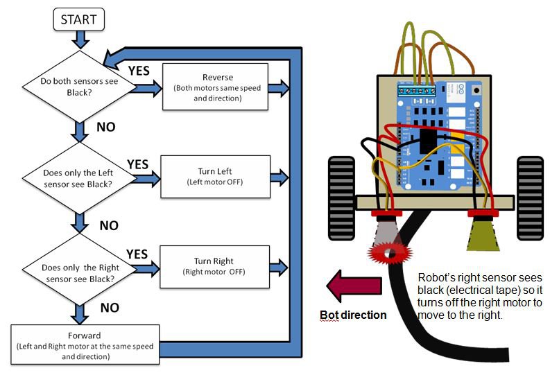
LOGIC OVERVIEW
The line following robot is programmed to basically avoid the color black. If both sensors see black, then the robot will back up until it no longer sees black. If one sensor sees black, then the robot will turn in the direction of that sensor until it no longer sees black. Other than that, if the robot doesn't see black on either sensor, it will simply move for- ward. In this application, the black line is created using common electrical tape. The logic for this algorithm is shown below along with a graphical representation of the front of the line following bot for reference.
SKETCH
/*
 9/10/2012
 Marc McComb

The line following robot is programmed to basically avoid the color black. If both sensors see black,
then the robot will back up until it no longer sees black. If one sensor sees black, then the robot will
turn in the direction of that sensor until it no longer see black. Other than that, if the robot doesn't
see black on either sensor, it will simply move forward. In this application, the black line is created
using common electrical tape.

This application uses the following hardware:
chipKIT™ Uno32 available at http://www.digilentinc.com/chipkit
Arduino Motor Shield available at: http://arduino.cc/en/Main/ArduinoMotorShieldR3
Sparkfun QRE1113 Line Sensor Board- Analog(Item #: ROB-09453) https://www.sparkfun.com/products/9453

Software used:
The Aruino Motor shield is designed for a PWM on pin 11. Since the Uno32 doesn't have a hardware PWM
on that pin, no worries, we just use Brian Schmaltzs SoftPWMServo library:
http://www.chipkit.org/wiki/index.php?title=Library_Status#SoftPWMServo_library

You will need to make sure that you add the library. To do this:
1) Make sure that you have a folder in your Documents:/MPIDE folder called Libraries
2) Copy the SoftPWMServo library folder from C:\mpide-0023-windows-20120903\hardware\pic32\libraries
    to the Libraries folder above
3) If MPIDE is open, close and reopen.
4) Now all you have to do is go to the MPIDE toolbar and select Sketch>Import Library>SoftPWMServo

More info on libraries at:
http://arduino.cc/en/Reference/Libraries

*/

#include <SoftPWMServo.h>

//Setting up the Hardware pins
// First the line following (IR) sensors
const int irLeft = 2; //Left line sensor is on pin A2
const int irRight = 3; //Right line sensor is on pin A3

//Setting up the Arduino Motor Shield
const int leftDIR = 12;
const int rightDIR = 13;
const int leftPWM = 3;
const int rightPWM = 11;
const int leftBrake = 9;
const int rightBrake = 8;
const char bothSpeed = 100; //sets how fast the motors will spin (0 to 255)

//Here we set up variable that will hold the ADC value representing the line sensor values
int leftSees = 0; //A2 ADC value (0 to 1023)
int rightSees = 0; //A3 ADC value (0 to 1023)

void setup()
{

  //Make sure to set all of our control signal pins as output
  pinMode(leftDIR, OUTPUT);
  pinMode(rightDIR, OUTPUT);
  pinMode(leftBrake, OUTPUT);
  pinMode(rightBrake, OUTPUT);

  //Next we make sure our brake signals are set LOW
  digitalWrite(leftBrake, LOW);
  digitalWrite(rightBrake, LOW);
}

void loop()
{
    //Start by reading the left sensor on A2
  int leftEye = analogRead(irLeft);

  //delay a little bit
  delay(5);

  //next read the right sensor connected A3
  int rightEye = analogRead(irRight);

  //Next, we run the motors based on the sensor reading

  //If both sensors see black (ADC value greater than 1000), then back up
  if ((leftEye >= 1000)&&(rightEye >= 1000)) reverse();

  //Otherwise, if only the left sensor sees black, then turn off the left motor
  //so the robot veer to the left
  else if ((leftEye >= 1000)&&(rightEye < 1000)) turnLeft();

  //Otherwise, if only the right sensor sees black, then turn off the right motor
  //so the robot veer to the right
  else if ((leftEye < 1000)&&(rightEye >= 1000)) turnRight();

  //Otherwise, move forward
  else forward();

}

//Turn right by turning off the right motor
//i.e disable the PWM to that wheel
void turnRight(void)
{
  digitalWrite(leftDIR, HIGH);
  digitalWrite(rightDIR, HIGH);
  SoftPWMServoPWMWrite(leftPWM, bothSpeed);
  SoftPWMServoPWMWrite(rightPWM, 0);
}

//Turn left by turning off the left motor
//i.e disable the PWM to that wheel
void turnLeft(void)
{
  digitalWrite(leftDIR, HIGH);
  digitalWrite(rightDIR, HIGH);
  SoftPWMServoPWMWrite(leftPWM, 0);
  SoftPWMServoPWMWrite(rightPWM, bothSpeed);
}

//Move forward by enabling both wheels
void forward(void)
{
  digitalWrite(leftDIR, HIGH);
  digitalWrite(rightDIR, HIGH);
  SoftPWMServoPWMWrite(leftPWM, bothSpeed);
  SoftPWMServoPWMWrite(rightPWM, bothSpeed);
}

//Reverse by enabling both wheels
void reverse(void)
{
  digitalWrite(leftDIR, LOW);
  digitalWrite(rightDIR, LOW);
  SoftPWMServoPWMWrite(leftPWM, bothSpeed);
  SoftPWMServoPWMWrite(rightPWM, bothSpeed);
}