chipKIT® Development Platform
Inspired by Arduino™
- Get Started
- Learning
- Products
- Blog
- Beginner
For first time users of chipKIT modules. - Intermediate
For users who have a moderate exposure with chipKIT modules. - Advanced
For users who are experts with chipKIT modules. - Developers
- About Us
- Support
Analog Read using MPLAB X IDE
Posted 2017-02-13 09:57:50 by MajenkoOverview:
In this project you will learn to use a basic functionality of chipKIT board in MPLAB X IDE, which is to read an analog value and output the corresponding digital reading for it. A potentiometer is a three-terminal resistor with a sliding contact that forms an adjustable voltage divider. Using a potentiometer measuring instrument, you could measure the electric potential. In this example we use the potentiometer in the chipKIT Basic IO shield. Find the same project using MPIDE here.
Hardware Used:
To do the analog read project, you require the following hardware devices.
- chipKIT Uno 32
- chipKIT Basic IO shield
- PICkit® 3 In-Circuit Debugger/Programmer
- USB cable
- 6 pin header to connect chipKIT board and PICkit® 3
Reference:
The reference guide for each board, schematics and other resources are available on their individual homepages:
- chipKIT Uno32 homepage at: http://www.digilentinc.com/Products/Detail.cfm?NavPath=2,892,893&Prod=CHIPKIT-UNO32
- chipKIT Basic I/O Shield homepage: http://www.digilentinc.com/Products/Detail.cfm?NavPath=2,892,936&Prod=CHIPKIT-BASIC-IO-SHIELD
Procedure:
-
Connect the hardware devices. The PICkit® 3 should be connected to the chipKIT Uno32 board through a suitable header and use the USB cable to connect the PICkit® 3 to your PC.
-
Place the IO shield on top of the Uno32 board with a bit of a firm press. A0-potentiometer of the IO shield will be used as peripheral for Uno32 board, in this excercise.
-
Once the hardware setup is made and the device drivers are updated for PICkit® 3 on your computer, launch MPLAB X (Start>All Programs>Microchip>MPLAB X IDE>MPLAB X IDE vx.xx on Windows® Machines ).
-
Create a new project through File>New Project. In the pop up new project window, select Standalone Project under Projects and click Next. Under Family scroll and select 32-bit MCUs (PIC32). Note the processor number from the chipKIT board's reference manual and enter it under the *Device * option. Click Next.
-
Select PICkit3 in the Hardware Tools, click Next. Select XC32 (v1.20) under Compiler Toolchains, click Next. Give a project name to create the project.
-
In the Project tab on the left side of the MPLAB X IDE, right click on Source Files > New > C Main File.. and give a file name for main source code. Once the dot c file opens, select all the codes in the file and replace it with the codes below.
#include <plib.h>
#include <xc.h>

#pragma config FPLLMUL = MUL_20, FPLLIDIV = DIV_2, FPLLODIV = DIV_1, FWDTEN = OFF
#pragma config POSCMOD = HS, FNOSC = PRIPLL, FPBDIV = DIV_1
#define SYS_FREQ (80000000L)

unsigned int channel4;  // conversion result as read from result buffer
unsigned int offset;    // buffer offset to point to the base of the idle buffer

int main(void)
{
    // Configure the device for maximum performance but do not change the PBDIV
    // Given the options, this function will change the flash wait states and
    // enable prefetch cache but will not change the PBDIV. The PBDIV value
    // is already set via the pragma FPBDIV option above..
    SYSTEMConfig(SYS_FREQ, SYS_CFG_WAIT_STATES | SYS_CFG_PCACHE);

    // configure and enable the ADC
    CloseADC10();    // ensure the ADC is off before setting the configuration

    // define setup parameters for OpenADC10
                // Turn module on | ouput in integer | trigger mode auto | enable autosample
    #define PARAM1  ADC_MODULE_ON | ADC_FORMAT_INTG | ADC_CLK_AUTO | ADC_AUTO_SAMPLING_ON

    // define setup parameters for OpenADC10
                // ADC ref external    | disable offset test    | disable scan mode | perform 2 samples | use dual buffers | use alternate mode
    #define PARAM2  ADC_VREF_AVDD_AVSS | ADC_OFFSET_CAL_DISABLE | ADC_SCAN_OFF | ADC_SAMPLES_PER_INT_9 | ADC_ALT_BUF_OFF | ADC_ALT_INPUT_OFF

    // define setup parameters for OpenADC10
    //                   use ADC internal clock | set sample time
    #define PARAM3  ADC_CONV_CLK_INTERNAL_RC | ADC_SAMPLE_TIME_15

    // define setup parameters for OpenADC10
    // do not assign channels to scan
    #define PARAM4    SKIP_SCAN_ALL

    // define setup parameters for OpenADC10
                // set AN2 as analog inputs
    #define PARAM5    ENABLE_AN2_ANA

        // use ground as neg ref for A | use AN2 for input A

     // configure to sample AN2
    SetChanADC10( ADC_CH0_NEG_SAMPLEA_NVREF | ADC_CH0_POS_SAMPLEA_AN2); // configure to sample AN2
    OpenADC10( PARAM1, PARAM2, PARAM3, PARAM4, PARAM5 ); // configure ADC using parameter define above

    EnableADC10(); // Enable the ADC

  while ( ! mAD1GetIntFlag() ) { } // wait for the first conversion to complete so there will be vaild data in ADC result registers

    // the result of the conversion is available in channel4.
    while (1)
    {

        channel4 = ReadADC10(0);          // read the result of channel 4 conversion from the idle buffer

    }

    return 0;
}
-
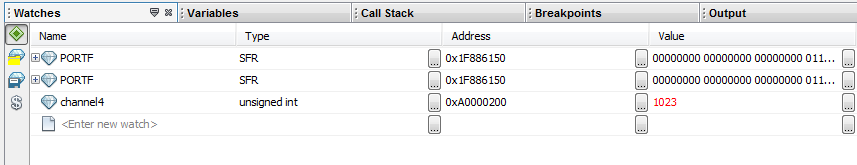
To read the potentiometer value, access the watch window from *Window > Debugging > Watches *or you can use the shortcut key *Alt+Shift+2. *In the watch window panel that opens on the MPLAB X IDE, enter the new watch as channel4, in the blank
area as shown below in the figure. 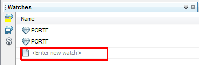
-
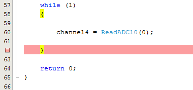
In the program editor window, put a breakpoint by clicking on the line number after the code line
channel4 = ReadADC10(0); // read the result of channel 4 conversion from the idle buffer
That is on the line with the closing braces of the while loop. This
should create a red box in the number line as shown in the figure
below,
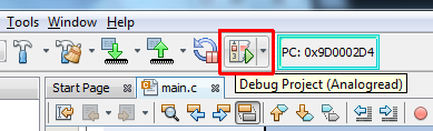
- Click on Debug Project icon shown below,
-
Once the program halts its execution at the line with the breakpoint, click on Watches output window, right click on the expand button under Value column and select Display value column as > Decimal. The value that appear in this column for channel4 variable corresponds to the potentiometer reading which is read in the range of 0 to 1023. A value 0 corresponds to 0 volts and a value 1023 corresponds to 3.3 volts.
-
Now, click on Continue button from the top pane and observe the value of channel4 to change and reflect the potentiometer reading as described before.
-
If you would like to change the potentiometer knob and see a different value, then, change the potentiometer knob and click on the *Reset *button on the top pane. This will initialize the variables back to zero. Clicking on the Play button on the top pane, will get your changed potentiometer value on the Watches window. Below is a screenshot showing the potentiometer value for 3.3 volts being read in the Watch window.