chipKIT® Development Platform
Inspired by Arduino™
- Get Started
- Learning
- Products
- Blog
- Beginner
For first time users of chipKIT modules. - Intermediate
For users who have a moderate exposure with chipKIT modules. - Advanced
For users who are experts with chipKIT modules. - Developers
- About Us
- Support
Analog read serial on OLED
Posted 2017-02-13 09:51:11 by MajenkoOverview:
In this project you will learn to use a basic functionality of chipKIT board, which is to read a analog value and output the corresponding digital reading for it. A potentiometer is a three-terminal resistor with a sliding contact that forms an adjustable voltage divider. Using a potentiometer measuring instrument, you could measure the electric potential. []
Hardware Used:
The hardware used in this tutorial will be a chipKIT Uno32 along with a chipKIT Basic I/O Shield both manufactured by Digilent Inc.
Reference:
The reference guide for each board, schematics and other resources are available on their individual homepages:
- chipKIT Uno32 homepage at: http://www.digilentinc.com/Products/Detail.cfm?NavPath=2,892,893&Prod=CHIPKIT-UNO32
- chipKIT Basic I/O Shield homepage: http://www.digilentinc.com/Products/Detail.cfm?NavPath=2,892,936&Prod=CHIPKIT-BASIC-IO-SHIELD
Procedure:
-
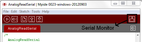
[Open MPIDE software on your PC and go to [File > Examples > Basics >][AnalogReadSerial] to open the code which reads the analog signal on serial window.]
-
The code should look like this:
/*
AnalogReadSerial
Reads an analog input on pin 0, prints the result to the serial monitor

This example code is in the public domain.
*/

void setup() {
Serial.begin(9600);
}

void loop() {
int sensorValue = analogRead(A0);
Serial.println(sensorValue, DEC);
}
The function Serial.begin(), sets the data rate in bits per second (baud rate) for serial data transmission. In this case, the baud rate for communication between the computer and the chipKIT board is set to 9600. Using analogRead function, enables the chipKIT board to read the input voltage at port A0 ranging from 0 to 3.3 volts into values ranging from 0 to 1023 (as chipKIT board has a 10 bit A/D converter in it). Serial.println function, prints in a new line each time the values from sensorValue variable in decimal format.
-
Make sure you connect the Uno32 board via the mini-B connector on board to an available port on your computer.
-
Place the IO shield on top of the Uno32 board with a bit of a firm press. LEDs and A0-potentiometer of the IO shield will be used as peripherals for Uno32 board, in this excercise.
-
Once connected, in your MPIDE window, select Tools>Board>chipKIT UNO32 to identify the UNO32 Board as the target
-
Next, select Tools>Serial Port>COMxx. This will depend on which port was assigned to the chipKIT UNO32 Board when first connected.
-
To load your sketch onto the chipKIT UNO32 board's Microcontroller, press the upload button. This will compile your sketch (check for errors) and then send to the Microcontroller. Unless you type your own code in the sketch, you wouldn't need to verify them before uploading.
-
Once the code is done uploading, open the serial monitor from the toolbar shown below,
-
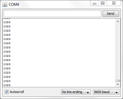
A new serial monitor window will appear as shown below,
-
The potentiometer on IO shield which provides input voltage to analog input A0 of UNO32 board, can be turned to get the varying voltage levels. Serial monitor window will show the decimal value change (between 0 to 1023) correspondingly.
-
As a next step, the Organic LED present in the IO shield can be used to display the potentiometer values. For this, go to the chipKIT Basic I/O Shield homepage mentioned in Reference section.
-
Download the zip file that contains libraries and documentation for using the Basic I/O Shield™ with the chipKIT MPIDE. Open the downloaded zip folder and copy the three IOShield folders in it. These three folders have the libraries and example programs for EEPROM, OLED and Temperature Sensor peripherals on IO shield.
-
Now open the drive where you installed the mpide software, inside your mpide folder navigate through hardware > pic32 > libraries and paste the three IOShield folders in it.
-
Close your mpide software, for the libraries to get included and the changes to take effect.
-
On restarting the mpide software and navigating through File > Examples; you can find IOShieldEEPROM, IOShieldOled and IOShieldTemp folders with their demo examples being included.
-
You can run the IOShield_Oled_Demo example as a new sketch, with the existing hardware setup, to observe the change in OLED display of IO shield.
-
To make the ADC values display on OLED, create a new sketch, save it by giving a name and insert the code below in the sketch space.
#include <IOShieldOled.h>

int adc_data = 0;
int thousands = 0;
int hundreds = 0;
int tens = 0;
int ones = 0;

void setup()
{
  IOShieldOled.begin();
  IOShieldOled.displayOn();
}

void loop()
{
  adc_data = analogRead(0);

  //parse data
  ones = adc_data%10;
  adc_data = adc_data/10;
  tens = adc_data%10;
  adc_data = adc_data/10;
  hundreds = adc_data%10;
  adc_data = adc_data/10;
  thousands = adc_data%10;

  //convert data to ASCII
   thousands = thousands+48;
   hundreds = hundreds+48;
   tens = tens+48;
   ones = ones+48;

  //Clear the virtual buffer
  IOShieldOled.clearBuffer();

  //Draw a rectangle over wrting then slide the rectagle
  //down slowly displaying all writing
    IOShieldOled.clearBuffer();
    IOShieldOled.setCursor(0, 0);
    IOShieldOled.putString("Analog read");
    IOShieldOled.setCursor(0, 1);
    IOShieldOled.putString("result is");
    IOShieldOled.setCursor(0, 3);
    IOShieldOled.putChar(thousands);
    IOShieldOled.setCursor(1, 3);
    IOShieldOled.putChar(hundreds);
    IOShieldOled.setCursor(2, 3);
    IOShieldOled.putChar(tens);
    IOShieldOled.setCursor(3, 3);
    IOShieldOled.putChar(ones);

  delay(100);

}
-
The above code gets the decimal valued data from the potentiometer in the IO shield, separates each number by modulo operation, converts the decimals into ASCII characters which are suitable OLED to read and displays it in OLED by assigning the cursor position.
-
To get more details on each function used with respect to OLED, open the IOShieldOLED folder which you downloaded from Digilent website and refer IOShield Library - Oeld.pdf
-
To get the display, verify the code and upload it to the board. Once uploaded, you can see the potentiometer value displayed on OLED. Turn the knob, to get values changing correspondingly.